I received a Seagate 7200.11 hard disk in a BSY (busy) state. The hard disk drive spins, but it’s completely invisible to the BIOS. Apparently all these models are affected by a bug in the drive’s firmware: ST31000340AS, ST3500320AS, ST3750330AS and others too.
I found this very well written guide on how to fix the BSY state on Seagate 7200.11 drive. I needed some sort of serial TTL adapter to hook up to the drive’s serial port, but didn’t have one at hand. Then I remembered that I have an Arduino clone Freeduino lying around and I knew that it already has a FTDI chip that does the USB to serial conversion for the Atmega chip. Ok, so it’s not technically Arduino AVR chip used to fix the drive, just the board.
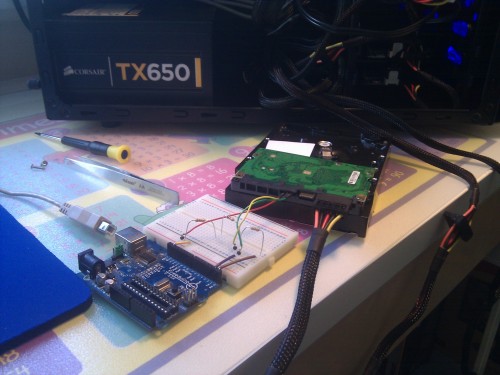
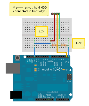
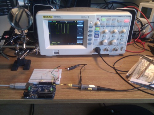
I removed the Atmega IC from the Freeduino board, hooked it up to an oscilloscope and tada! USB to serial works, but it’s 5V. No worries, just need a basic voltage divider for the RX line on the drive to drop it down to roughly 3.3V. There is no need for the voltage divider on the TX line from the drive, because FTDI chip understands 3.3V as HIGH input.
A quick schematic to hook everything up is below. Please note, that PIN0 is used for TX and PIN1 is used for RX!
A quick check on the oscilloscope to make sure that voltage is in accepted range:
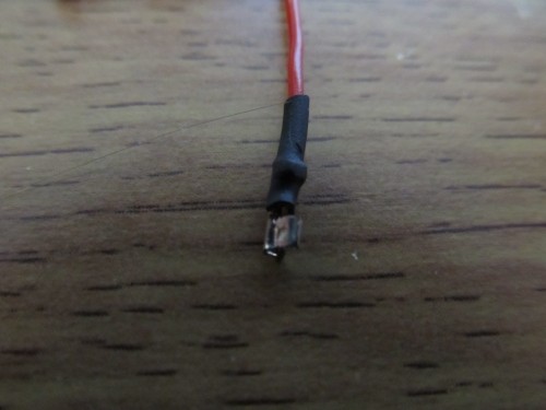
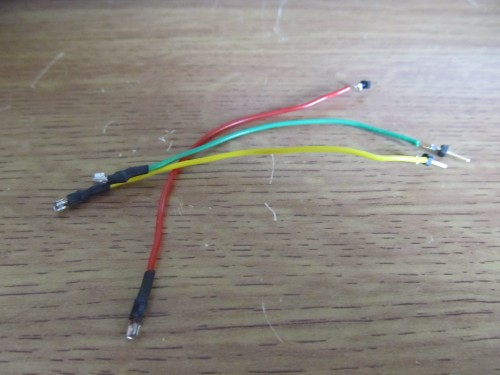
I didn’t have proper connector for the drives serial pins, so made my own:
The metal plates were taken out of another connector that I had lying around, I soldered pins to make it easier to plug the wires into the breadboard.
Then I simply used the COM port registered by the Arduino/Freeduino board’s FTDI chip to communicate with the hard drive and recover it from BSY state with the guide mentioned at the beginning of the post to fix the drive.
I also got into one road block. When I was trying to spin up the drive I got the following error:
F3 2>U

Error 1009 DETSEC 00006008
Spin Error
Elapsed Time 22.207 secs
R/W Status 2 R/W Error 84150180
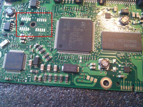
This happened because the HDD connectors did not properly hook up to the logic board when I removed the piece of paper. They seemed to be very oxidized. I had to shut everything down, take out the board and scrape the contacts with a very sharp knife and start over.
Once the data is recovered, I don’t recommend using the drive and suggest properly disposing of it.
A few more links about fixing this issue using alternative hardware:
Hmmm well i use a usb to serial adapter to hook up to serial port of the hard drive everything’s set up and i opened hyper-terminal and choose com port and made settings but the problem is its automatically typing special characters and it endless any help really appreciated….i’m really in need of that data…..:-)
What kind of USB to serial adapter are you using? Would you be able to provide a picture of it?
Mine also cycled through endless special characters. It’s a Micro SATA Cables – USB 2.0 to TTL UART 6PIN Module Serial Converter CP2102. Image: http://lghttp.27756.nexcesscdn.net/80BBFD/magento/media/extendware/ewminify/media/inline/57/5/usb-ttl-adpt_1.jpg
Can I use Raspberry Pi?
In theory yes, but you would need a library to use the GPIO pins as serial communication device and make sure that pins are 3.3V, otherwise you would need to use a voltage divider just as I did with Arduino.
I just fixed my 7200.11 with a raspi, nothing extra need just connect a wire from GRD, GPIO 14 (TXD), GPIO 14 (RXD) to the drive. You also have to configure your pi to not use serial for console (http://www.hobbytronics.co.uk/raspberry-pi-serial-port)
after that use minicom or screen to connect to the serial device
and the other thing is how do you get this thing {F3 2>U
Error 1009 DETSEC 00006008
Spin Error
Elapsed Time 22.207 secs
R/W Status 2 R/W Error 84150180 }
I’m using arduino uno, i thought it was serial comand thing
i need to know that there is a different between in your 1st figure and the 2 schematic figure( wire diagram).
And I got a samsung hard drive and the problem is it’s spinning only first 30sec, and it’ll get suddenly stopped. Do you think that i can recover my hard drive in this way???.. Pls help me!!!!!!!
The schematics is identical to the one in the picture.
I seriously doubt that your Samsung drive is suffering from the same fate. You might have to start by looking at your model number and googling if anybody had similar issues you are having.
Hi,
in your picture the voltage divider is on PIN0 and is connected to the HDD midle pin (RX) and PIN1 is connected directly to the HDD rightmost pin (TX), while in the schematics the voltage divider on PIN0 is connected to the HDD rightmost pin (TX) and PIN1 is connected directly to the HDD midle pin (RX).