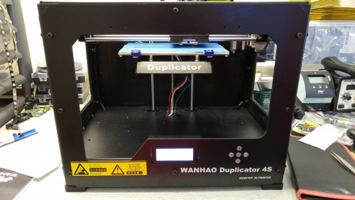
Recently I bough a faulty Wanhao Duplicator 4S to increase the capacity of my 3D printing requirements as I already own one and know the machine inside out. eBay seller’s description wrote that the 3D printer stalled in the middle of a print. I did some digging across the internet before I purchased the machine and was suspecting that some wires were not shielded correctly which resulted in electromagnetic interference. It cost me £300 and that’s half of the retail price so even if I couldn’t be able to fix it, I would have plenty of spare parts for my current 3D printer.
Tag: electronics
Going beyond just a hobby
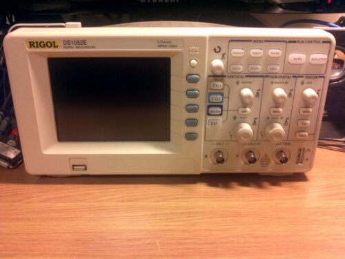
So I finally decided to take a plunge to make an electronics hobby into something more, maybe a full-time job. As one of the first things to getting there I bought the Rigol DS1052E digital oscilloscope. Decided to buy this one because it’s hackable: with a small firmware update it should be possible to make this 50MHz scope into a 100MHz one. Apparently this is the same hardware as DS1152E, just firmware needs to be updated to transform it into a twice more expensive instrument! More about this in another post.
A bunch of electronic parts are coming from China in the next couple of weeks (hopefully). Very exciting times indeed!
Arduino interfacing SRF05 rage finder with LCD screen
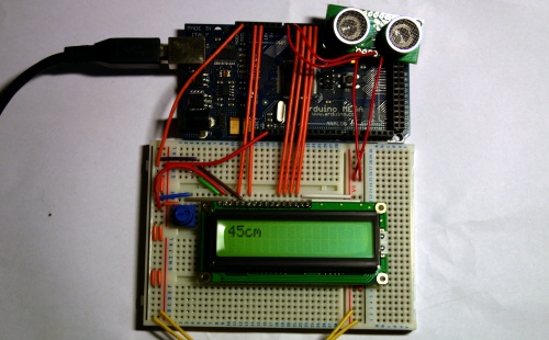
This is a another sample demonstrating Arduino MEGA, LCD screen and SRF05 ultrasonic range finder. The distance measurement from SRF05 is displayed on the LCD screen in centimetres.
[youtube]http://www.youtube.com/watch?v=VNJu6oR69Zs[/youtube]
Different from Infra Red range finder witch uses IR light to measure distance, ultrasonic range finder sends short high pitch sound pulses and measures the time for the echo to come back to the microphone. Here is a very good comparison of the two types of range finders. The code running on the Arduino:
// include the library code:
#include <LiquidCrystal.h>

#define echoPin 6             // the SRF05's echo pin
#define initPin 7             // the SRF05's init pin
unsigned long pulseTime = 0;  // variable for reading the pulse

// initialize the library with the numbers of the interface pins
LiquidCrystal lcd(12, 11, 5, 4, 3, 2);

void setup() {
 // set up the LCD's number of rows and columns:
 lcd.begin(16, 2);

 // make the init pin an output:
 pinMode(initPin, OUTPUT);
 // make the echo pin an input:
 pinMode(echoPin, INPUT);
}

void loop() {
 digitalWrite(initPin, HIGH);
 delayMicroseconds(10);
 digitalWrite(initPin, LOW);

 pulseTime = pulseIn(echoPin, HIGH);

 lcd.setCursor(0,0);
 lcd.print(pulseTime / 58, DEC);
 lcd.print("cm");

 delay(100);
 lcd.clear();
}
Another application for SRF05 is a basic theremin by LuckyLarry. You can see it in action here:
[flickrvideo]http://www.flickr.com/photos/peplop/4083266594[/flickrvideo] [flickrvideo]http://www.flickr.com/photos/peplop/4083675920[/flickrvideo]
Read on here:
Arduino MEGA auto-reset fix
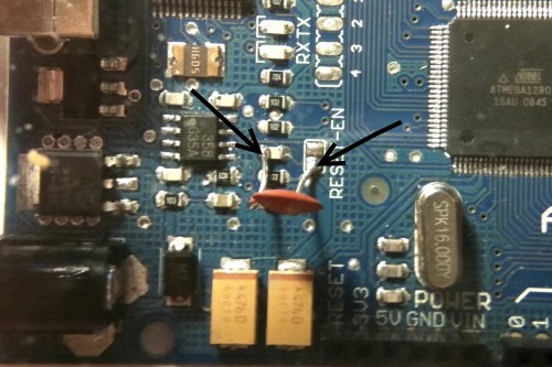
The Arduino MEGA I got had and issue with automatic reset during sketch upload. The error message in the Arduino IDE looked something like this:
<pre>avrdude: stk500_getsync(): not in sync: resp=0x00
avrdude: stk500_disable(): protocol error, expect=0x14, resp=0x51
I had to hit Reset button just before uploading a sketch. This issue was due to some sort of defect in the Reset capacitor. The fix is very simple: just solder a 100nF capacitor on top of the defect one.
(via)
Arduino LED traffic lights
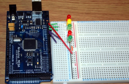
This is a bit enhanced version of the “hello world” blink application for Arduino: traffic lights emulator. The top three LEDs control car traffic and the bottom two are fore pedestrians.
int carRedPin =  13;
int carYellowPin =  12;
int carGreenPin =  11;
int pedestrianRedPin =  10;
int pedestrianGreenPin =  9;

// The setup() method runs once, when the sketch starts

void setup()   {
  pinMode(carRedPin, OUTPUT);
  pinMode(carYellowPin, OUTPUT);
  pinMode(carGreenPin, OUTPUT);
  pinMode(pedestrianRedPin, OUTPUT);
  pinMode(pedestrianGreenPin, OUTPUT);
}

// the loop() method runs over and over again,
// as long as the Arduino has power

void blink(int light)
{
  digitalWrite(light, LOW);
  delay(500);
  digitalWrite(light, HIGH);
  delay(500);
  digitalWrite(light, LOW);
  delay(500);
  digitalWrite(light, HIGH);
  delay(500);
  digitalWrite(light, LOW);
  delay(500);
  digitalWrite(light, HIGH);
  delay(500);
  digitalWrite(light, LOW);
}

void loop()
{
  digitalWrite(carRedPin, HIGH);
  digitalWrite(pedestrianGreenPin, HIGH);
  delay(3000);

  blink(pedestrianGreenPin);

  digitalWrite(pedestrianRedPin, HIGH);
  digitalWrite(pedestrianGreenPin, LOW);
  delay(1000);
  digitalWrite(carYellowPin, HIGH);
  delay(1000);
  digitalWrite(carRedPin, LOW);
  digitalWrite(carYellowPin, LOW);
  digitalWrite(carGreenPin, HIGH);
  delay(3000);

  blink(carGreenPin);

  digitalWrite(carYellowPin, HIGH);
  delay(2000);
  digitalWrite(carYellowPin, LOW);
  digitalWrite(carRedPin, HIGH);
  delay(1000);
  digitalWrite(pedestrianRedPin, LOW);
}
The code above is straightforward: just enabling and disabling LED at certain time. Traffic lights in action:
[youtube]http://www.youtube.com/watch?v=f4jVitaSPGg[/youtube]
Arduino and LCD screen
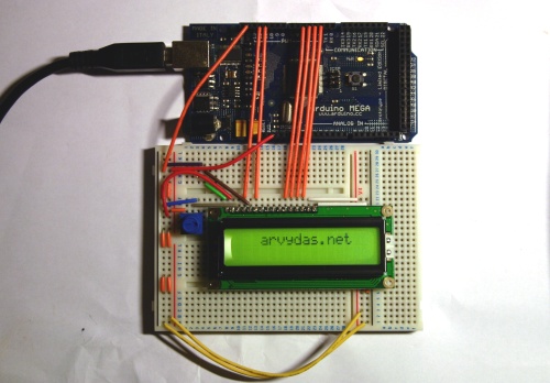
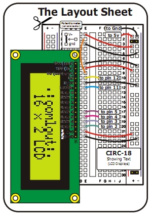
This was one of my first projects to try out various features of Arduino. I got this 2×16 LCD screen from Oomlout. The breadboard schematics came together with the LCD screen and is relatively simple.
Here is the sample code I uploaded to the controller:
// include the library code:
#include <LiquidCrystal.h>
// initialize the library with the numbers of the interface pins
LiquidCrystal lcd(12, 11, 5, 4, 3, 2);
void setup() {
// set up the LCD's number of rows and columns:
lcd.begin(16, 2);
}
void loop() {
lcd.print(" arvydas.net");
lcd.setCursor(16,1);
lcd.autoscroll();
for (int thisChar = 0; thisChar < 28; thisChar++) {
lcd.print(" ");
delay(250);
}
lcd.noAutoscroll();
lcd.clear();
}
Just a simple scrolling text and here is the video:
[youtube]http://www.youtube.com/watch?v=hTJQqKEdKlE[/youtube]
Robot logic
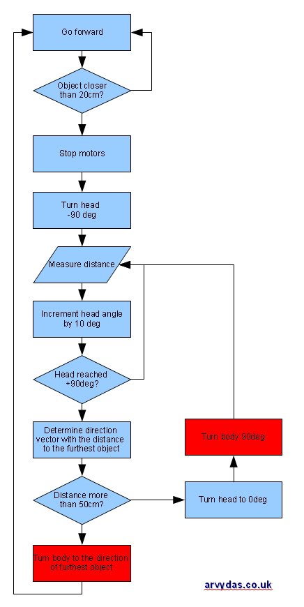
Started thinking about the logic for the robot. The first one that I used in my prototype from LuckyLarry’s website seems to be too basic, so I did a quick brainstorm and came up with the flowchart above. The logic adds the complexity of using a range finder sensor on top of the servo. Robot should drive forward, unless it encounters an obstacle closer than 20cm. Then it should stop, look around and determine the next free path it should go. The most challenging bits are the ones that I colored in red: this requires some sort of sensory “knowledge” of the direction of the robot. If I had a spare accelerometer, everything should seem more simple: just get the data from the accelerometer and calculate the direction of the robot when it turns. All I have now is just SRF05 range finder so another thought came to my mind. At the point after robot scans the surrounding area, it should know the distance to the surrounding area with 10 degree resolution. For example:
- -90 deg | 70 cm
- -80 deg | 60 cm
- -70 deg | 50 cm
- -60 deg | 50 cm
- -50 deg | 40 cm
- -40 deg | 40 cm
- -30 deg | 30 cm
- -20 deg | 20 cm
- -10 deg | 20 cm
- 0 deg | 20 cm
- 10 deg | 20 cm
- 20 deg | 20 cm
- 30 deg | 20 cm
- …
According to the logic, robot should choose path (1) by turning -90 degrees. Considering that before the turning head is facing 0 degrees, it should continue turning, until it determines that the distance is more than 70cm to the closes object, so the range finder should read all the way from 20cm to 70cm with a threshold of +-5cm.
Huh, seems that hardware setup was the easiest bit. Building smart software to run the robot is a bigger challenge and that’s what makes this project so interesting. :)
