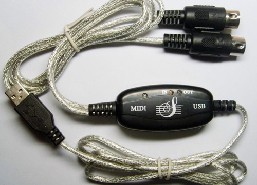
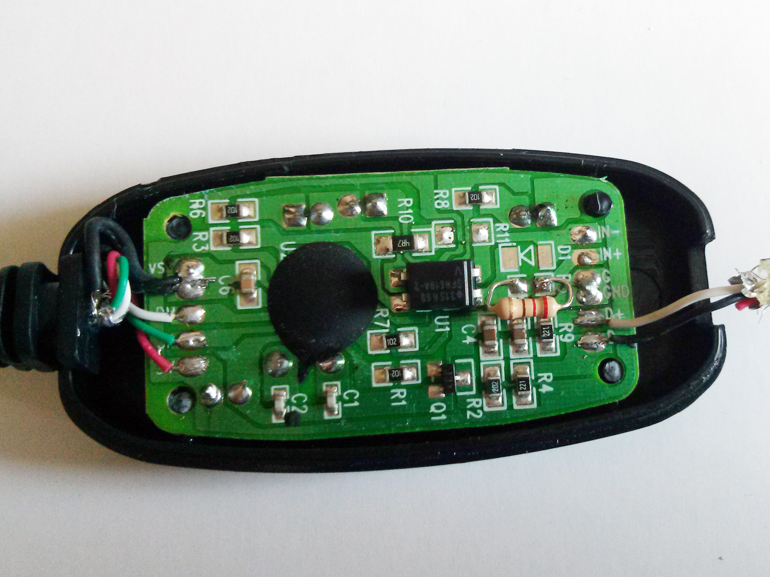
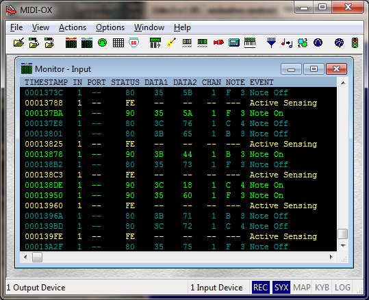
I had recently bought a Rock Band 3 Wii keyboard which has come down in price to around £10 with an intention to connect it to a cheap Chinese USB to MIDI interface cable for around £3 pictured above to do some MIDI experiments on my computer. Videos online demonstrated that connecting the IN connector to the keyboard and USB cable to the PC was all that was needed to use it, but I just couldn’t get it working. The Rock Band keyboard detected a MIDI cable and switched to MIDI mode, PC properly detected USB MIDI device, but there were no messages in the MIDI-OX application. That’s when I decided to open up the plastic casing to find a few surprises…
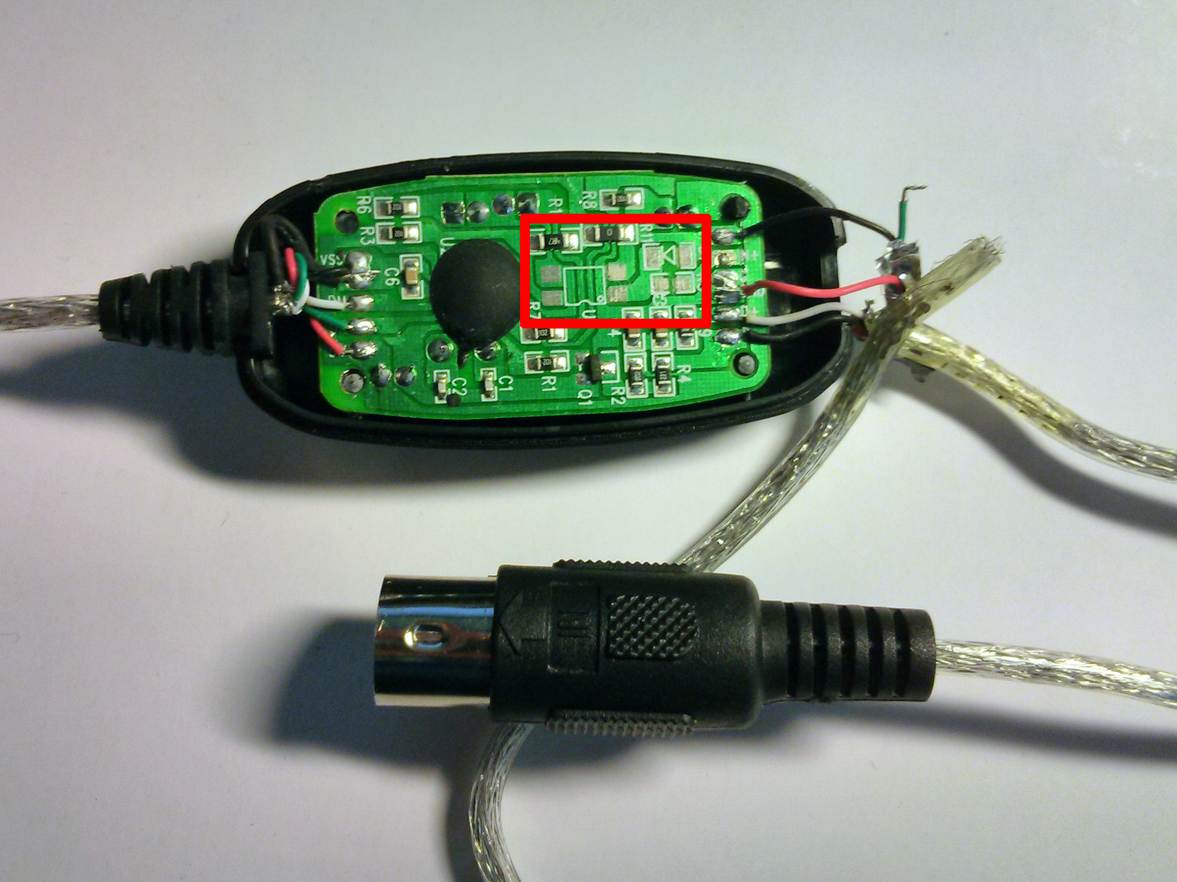
First thing I noticed, were the missing components on the board pictured in the red square. After further investigations, it turned out that the wiring was done completely different to the MIDI specifications. Here is a very rough schematic of how it’s done and how it should have been done:
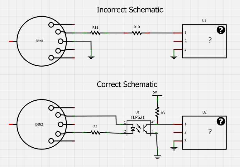
The MIDI specification requires an opto-isolator to completely isolate MIDI connected circuits. The USB cable did not have these parts populated and used a common ground for signal transfers. Rock Band keyboard probably was not expecting this. No wonder it did not work!
So, I went to Maplin and purchased a low-current opto-coupler SFH618-2 for £1.39. A quick assembly on the breadboard and a bit of soldering for ground, 5V and data lines to get to this:
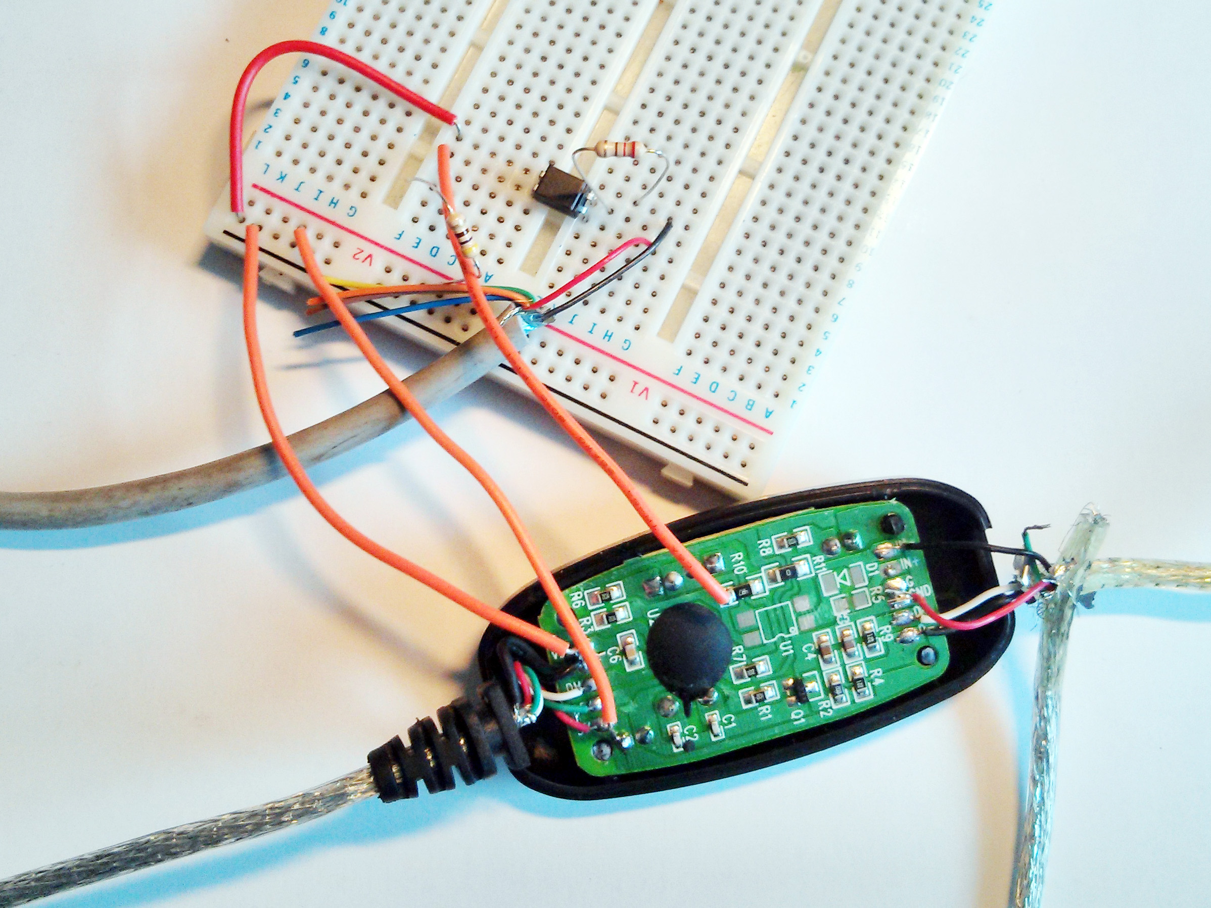
And it worked! It was finally time to populate the missing components:
- Got rid of the R11
- Soldered opto-coupler in U1 and it was a perfect fit for the pinout. I only had to shorten the pins to mount it as close to the board as possible.
- Soldered a 220 Ohm resistor in R5
- Removed the red DIN connector wire completely from GND connection and trimmed it
- Soldered the black DIN connector wire to IN- pad
- Soldered the green DIN connector wire to IN+ pad
The case fit back perfectly, though required some glue to hold in place and MIDI-OX finally came to life!
This USB MIDI cable might be a cheap and quick way to add USB enabled MIDI for Arduino, but I’m really wondering if it would have worked with any MIDI device at all due to incorrect wiring. You get what you pay for: some self assembly may be required.
There are a lot of model of this cheap usb 2 midi converter, I bought nearly every models and try, only one model can work, finally I decide to make my own converter using the ch345chip, no more missing component, should work fine.
Hi! Did you try it with Apple devices? I tried to connect it to iPad via lightning cable, but I got a message that says ” inte false is not supported “
I was pulling my hair out, opened my device like yours and found like yours no opto coupler fitted, fitted like you on breadboard all working. i used a 6N137 because that’s all i had in stock.
Hi, VERY USEFULL tech solution!
Also my cheap USB2MIDI cable (from China) has the same problem.
But also here I have only the opto-isolator 6N137 that has got 8 pins.
Can anybody help me understand if the following connections are correct?
Looking to the image in the post:
Upper Left –> pin2 [6N137] pin7 –> Upper Right
Lower Left –> pin3 [6N137] pin6 –> Lower Right
In fact the optoisolator 6N137 has 8 pin (4 per side).
Please help me…
6n137 is very fast (ton and toff in nsec), but it is an 8 pin chip. Did you have some problem to install it?
Rene
Hi, awesome article.
I have pretty much the same device, but I notice that mine is missing another component. I think it might be a capacitor, the component is usualy found on the back side of the circuit board and is marked C3. Can anyone please possibly tell me what cap I’m supposed to use there? Thanks in advance.
just looked, Sorry no C3 on my device
Thanks a lot for checking… I figured it out on my own after a while of testing. The device is working as it should now, but it still can’t do the things I bought it for. I’ll buy one of those fancy “Uno” midi to usb cables some day when I have cash, appearently it will work…
Thanks anyway for the help.
Thank you! Have just ordered the Maplin component and will have a bash at this. Thank you very much for posting both the maplin link and the photos – very useful. I seem to spend my life soldering tiny things these days!!
PS when you say you got rid of R11 did you also bridge the pads or just remove the resistor?
To add to my last comment, yes, you need to bridge R11. If you don’t you get all sorts of note-off messages which are on different octaves and sometimes different notes / channels. I think one person mentioned this. Anyway, if you have this issue, just bridge R11 as well as doing the other stuff.
Are you sure? I am looking at picture of forward post (last for now) of firehacker and I see no bridge on R11.
After fix: https://pp.vk.me/c638616/v638616760/c430/f6y5k2YxkiI.jpg
So please who solved can say please if the bridge is necessary?
If you’ll make the bridge you’ll bypass the opto and you will send incorrect current direction, so no, you don’t need the bridge.
P.S. I haven’t solved, sadly
Bye
Hi,
I recently bought two of these adapter cables, both labelled differently, but using the same PCB with no opto-isolator fitted.
Before I go to the trouble of ‘upgrading’ them, can anyone tell me why the none of the USB ports on my new HP desktop don’t fall back gracefully to work on these and many other USB 2 devices which I own?
Even the two ports which are labelled USB2 suffer the same problem.
Use a passive usb hub on those ports. I own a cheap (Chinese – sigh) USB ASP adapter that does not work on any port of my laptop as long as I do not connect it via a cheap (Chinese – grin) usb hub.
Bloody Chineese piece of … argh…
It seems that it does not only violate MIDI specification (absent opto-isolation), but corrupts SysEx messages sent via the converted as well. So you can’t upload patch dump into your synth from your PC, for example.
Going to connect my oscilloscope and check what happens to SysEx messages right now.
Hi,
What’s your advice re a USBMIDI interface for MacOS that behaves well (i.e. full SysEx reliability [SysEx xfers from my Roland VG8 aren’t the right length and are mangled] and optoisolation)?
Thanks,
Elliot
That’s a shame about the SysEx side of this thing. I just got one with the optocoupler and all, but it either omits bytes or corrupts SysEx streams. Got another coming this week where the LEDs are oriented a little differently, but I won’t get my hopes up. SysEx is a deal breaker here.
It does seem there are working ones out there, just wish there was a way to tell which was which.
Hello, thank you for the very informative post. I recently purchased a cable identical to yours. The circuit was exactly like yours in the first picture. The only differance is, mine has both a midi in and a midi out cable. When I first connected it the device I connected to my PC (A Pod 2.0 in case that matters), could send data to my PC but it would not receive anything.
I tried your solution above but desoldering R11, even though I connected everyhting else as shown, broke the out connection as well. The In connector is soldered to the IN- and GND connections, while the OUT is soldered to D+ and D- connections. Note that I need to connect the OUT cable to the IN connection of my device etc.
Any suggestions on if and how I could make this work would be great.
Angel K, your description of your case is so hard to understand…
The pair of wires going to MIDI IN jack must be rewired: one wire to IN–, another to IN+. Nothing should be connected to GND, connecting to GND can damage your music equipment in worst case.
R11 must be desoldered, U1, R5 and D1 have to be installed.
I have just fixed mine.
Before fix: https://pp.vk.me/c638616/v638616760/c41c/_cSLkU5kUR0.jpg
After fix: https://pp.vk.me/c638616/v638616760/c430/f6y5k2YxkiI.jpg
Hi,
for me the fix did not working.
The only difference is in opto PC817 (Maybe this component is not fit for this purpose?) and I haven’t used diode D1.
Any suggestions?
Regards
Siro
Ah thanks I’ll try that. What did you solder in ?
What did you solder in D 1… it was cut out from my previous comment somehow.
My pc can send data to the keyboard but the reverse does not occur, as if my pc was a “master” keyboard linked to “slave” keyboard (actual keyboard). My midi cable is also missing C1, C2, opto and R5
it also does not appear as USB 2.0 Midi but a USB A device among the midi devices.
Mine is same problem: PC to keyboard is okay, but keyboard to PC is not functioning.
i checked the opton-isolators used in previous posts. What I have done is :
1. 817 optonisolator
2. 220 ohm resistor
3. remove 0 ohm resistor
4. A2 unknown smd diode (and tried 1N4148 diode, same result)
5. relocate the red wire (keyboard out) from GND to IN+(marked on the PCB board)
If anyone knows which I ‘ve done is wrong, please kindly give a post.
Hi, I know exactly what’s your problem: 817 is too slow. It cannot handle the Midi frequency ( 31250 rate ).
You have to choose something like 357t, 6N137/6N138 or SFH618A-2
Regards
hi there, thanks for your comment, I’d try it this weekend.
thank you so sincerely~
Hi, ResidentEvil… did it work for you change the opto isolator for any of the suggestions of Siro?
I use PC817 as well, still not working (the fix managed to get data sent to MIDI-OX, but the data is still wrong). Can’t find any info in the datasheet about how much bps it can handle, how did you know that it was 817 that’s causing the problem?
My errors with 817 (MIDI-OX output):
When I press any key, it did say note on, but it’s always C -1 note (normally it should be A 4, G 2, etc… right?) also for every note on, there’s always 4 to 6 note off. All of this happened with only 1 key press (I haven’t even lifted my finger from the keyboard, note off shouldn’t even appear in the first place)
Anyone?
Siro massive thanks! I changed the optocoupler to PC123, and it works fine!
for anybody in need of an explanation (kinda), you can google PC817 and PC123 datasheet. There is a graph with resistor value in x-axis and RESPONSE TIME in y-axis. You can see that PC123 has less response time (faster) than PC817 with the same resistor value. Somehow it makes PC123 able to communicate in MIDI data rate (not sure if I’m using the right words, also can anybody do the math?), while PC817 can’t (has errors I described in my previous comment).
why not 357t? My local electronic shop only has PC123. Also, if you compare response time from both datasheet, it’s kinda similar. I can guarantee you if PC123 works, 357t will. Just remember, DON’T use PC817
Confirmed. Using the PC123 the cable works perfectly.
Hi Siro, i can not find any of those elements, is it ok to go with SFH620A-3 ?
thank you
This adapter doesn’t work with all devices.
I have two pieces, one equipped with a SFH618A-2 and one with a 357T.
Both are working fine with a new Thomann DP25 but receiving only crap with a old Roland E20.
I also have a third one i bought some years ago which looks identical but has a whole other pcb:
http://imgur.com/jtRCVkv
This one works fine with all tested devices.
OMG! You saved me. I have been *plagued* by the fact that one of my MIDI devices just wouldn’t work with my cheap generic USB MIDI cable – all my other ones work fine… and further… *from* my computer works fine to the device in question, but the *output* from this one device doesn’t. I saw your post and cracked it open… Identical!! Now I just need to get the right components.
THANK YOU!!
There is 5 volts in MIdI IN connector pins 5 and 4 when there is not optoisolator. And no voltage when there is an opto-isolator.
There are two power supply, one is the PC 5 volts which feeds the interface through the USB port, and the other power supply is the 5 volts within the MIDI encoder, which may comes from a wall adaptor. This 2 power are floating one to each other, they do not share a common. But the cheap interface couples the signal by 2 resistors, so it needs that the two power supply must share the common. That could be the problem on cheap interface. I will try to join both common by a third lead in MIDi IN cable and will see.
Bingo. There is no need to install an optoisolator. Just connect a ground third wire to central pin on MIDI IN DIN connector and rewire one lead to in(-). So that both power supply, USB and MIDI device shares the same common (Cheap interface MIDI IN cable has only two wires but MIDI OUT cable has 3 wires and could be used)
Can you please show a picture of your wiring?
I have read through the article and the posts. I got quite confused by the variations in components and results obtained. R11 – To bridge or not to bridge? D1 – yes/no? what component is it? value? Wiring – which colour goes where?
Can we have clear final photos of the board, components used and correct wiring for those that did work?
Mark B
The problem is that resistor coupling instead optoisolator needs both power supply, Midi Source and Midi Interface shares the same ground and this is not happening in cheap devices. The black wire connected to “G” is coming from pin 4 insted pin 2 in Midi In connector. Usually Midi Sources female connector has a ground in pin 2.
So don´t do anything inside interface and just make a jump between pin 2 and 4 of MIDi IN connector wraping a small piece of wire and then pushing inside.
Thanks
Rene Manzano
I cannot put images here.
Email:
Hello,
I have the same cheap CH345 midi adapter and it isn’t working either (the OS sees it though). It’s not identical to yours but it also has the U1 trans-optor missing. Could someone please take a look at these pictures here: https://imgur.com/a/9AXAI and tell me how to make this thing work? Thanks.
R5 220ohm
U1 optocoupler e.g. SFH618 PC123
D1 1n4148
after adding optocoupler, Maybe R1 need to removed
CMIIW
Black wire soldered to “G” is coming from pin 4 MIDI IN male connector and should be coming from pin 2 . Try to make a jumper between pin 4 and pin 2 . It is not easy but someone did it and it worked OK.
Hi there.
In my case, pin 4 MIDI IN male connector is the black G and pin 2 MIDI IN is the red one, soldered on IN-. It doesn’t make any sense to connect both.
The USB GND black wire is common to this MIDI IN G black one, but I don’t have a optocoupler, nor diode, nor R11 in the board, just R10 going to the main chip.
And to make things worst, I only got a PC817C in hands to try.
Here:
http://i.imgur.com/wKH8ZsB.jpg Of course I took the pic with the board upside down. 🙄
On the left, from below:
– MIDI IN – (red cable)
– MIDI IN + (not connected to any cable)
– G (black cable connected to MIDI IN male connector cable)
– MIDI OUT male connector, a black cable connected to D+
– MIDI OUT male connector, a red cable connected to D-
Thank you for posting! Very helpful.
Guys,
I have come across the same situation as you with a cheap chinese USB MIDI controller based on the infamous CH345 chip.
Before you perform any modification on your PCB, I would recommend that you understand the fundamentals of an optocoupler. The output of an OC is basically a transistor which Base is fed by an emitting diode. Now, this transistor will work only if its collector is powered through a resistor from USB +5V. If this resistor is not installed the OC will obviously NOT work.
Summary :
1) There should be no common ground whatsoever between keyboard side and USB side, the purpose of an optocoupler is to get things fully isolated one side from the other.
2) Make sure that Pin 3 (normally, please check datasheet of OC) is fed by something like 1K or 2K ohm. I believe 1K is enough. On Joseph’s picture, it does not appear very clearly, but it seems to be R3, please inspect carefully, I may be wrong from the distance with only one picture.
3) Systematically install a protection diode (1N4001, 1N4004, 1N4007, 1N4148, whatever) in parallel to Pin 1 and Pin 2 of the OC.
3) Install a 220 ohm or 330 ohm resistor to feed the emitting diode of the optocoupler. Personnally, I have put approx. 300 ohm that allows about 5mA through the emitting diode of the photocoupler, and with a CTR of 100% I have approx the same current through the transistor, which is enough to saturate it with a collector resistor of 1kohm when MIDI signal come in.
4) Make sur that the input wires are properly connected to IN+ and IN- only and this, the right way (not in a reverse way, or it will not work) Please remember that MIDI output and OC output are opposite logic.
5) Nothing should be connected to GND for at least 2 purposes : a) isolating MIDI side from USB side and b) avoiding ground loops.
And it should work, probably whatever the OC is, i.e. PC123 (works for me) or PC817 or EL357.
Good luck.
Hi,
Amendments to my previous post :
1) In order to better fulfill Midi standard, I installed 220 ohm instead of 300 ohm to feed the diode of the optocoupler.
2) For final version I have now installed an SMD EL357 optocoupler instead of temporary through hole PC123.
3) It appears that feeding the transistor of EL357 with 1K or 2 2K does not allow the interface to work properly. I’ve had to go down to about 250-400 ohm in order to achieve a good and stable output from the interface. I finally installed 330 ohm.
4) I have cut some traces and performed some wire bridging in order to have the right lighting of LEDs with reference to the indications on the front side of the interface (i.e. Power on, Midi In and Midi Out).
Picture after upgrade here : https://imgur.com/FN7SFjE
Caution : there was originally a resistor on R10 (in line with R11=0 ohm), that resistor was supposed to compensate for the absence of optocoupler. I obviously removed this resistor when I decided to put an optocoupler instead.
Good luck.
Thank you for this, I went back to the store that i bought it and dared him that if theres is missing components he has to give me a more expensive working cable, he took the bet and I won and now I have a 50 dollar midi to usb cable :D
Hi, dears!
I came from Poland and my english is poor.
I want to thans All users on this forum but especially thaks you – Pierre. I have the same elements missing as You. In this midi controller light red diode and no work, but OS (Windows) on computer detect properly after plug into.
I wrote this message, because instead optocoupler EL357 I’ll experimentally insert element as number 480 (in electronic shop EL357 was absent, so I will take that). Properties of diode and resistors I will take from Pierre secondary post. I’ll cut off “+” path to red diode and link “+” this diode to R6. First I’ve try to not cut off this place, then controller work totally incorrect.
Now this controller is working good, don’t mess messages between midi keyboard to computer and not have delay. Middle diode (blue) squint when I play.
Now I cannot to put the foto from this operation, but if You interest You can write to me:
So, one more I want to thank You for instructions. Now I am happy.
I do not understand the first attempts, those with the cables. Is it possible to works with no chip?
I try with 6N137 but no luck :(
The midi signal led blink when send data from keyboard but to the DAW do not receive anything. No any error on my PC. Also first led flash when DAW is open/close
Trying to read data from Device Monitoring Studio see nothing, the device do not send any data only when connect/disconnect.
GabyL, if I remember correctly, MIDI signal blinks mean that the optocoupler is working (the optocoupler output signal is generated successfully), so it might be something as simple as wrong cable soldering in the output connector. I mean, seems like the input connector is soldered wrong from the factory, chances are the output is wrong too lol. I’ll upload the pic of my working cable later (in case you / someone else still need it)
Peter, I’m no expert but I tried making it work without optocoupler. Failed. Tried installing an optocoupler (PC817), failed again. Then as suggested by Siro (see comments above, Dec 2016), succeeded with other optocoupler (PC123). Your local electronics store may have different optocouplers. Some will work, some will not. To make things worse, we don’t even know if our cable electronics have the same resistors / connections / configurations. Some advice above will work, some will not. In any case, good luck
-It’s amazing how this post was from 2013, but still has interest from people in late 2018 (and probably 2019 too lol). God bless this website.
So what is the final solution?
Put an optocoupler or simply jumper pin 2 and pin4?
Thank you
Peter
Thanks for posting. Explains why my older “chea p” worked – they had an opto-coupler and were wired correctly plus could handle some long Systex (800kb broken into 512 byte buffers) and later versions didn’t work – you guessed it (exactly same as above).
Ordered original opto suggested [SFH 618]
Got rid of the R11 [check]
Soldered opto-coupler in U1 and it was a perfect fit for the pinout. I only had to shorten the pins to mount it as close to the board as possible. [check]
Soldered a 220 Ohm resistor in R5 [check]
Removed the red DIN connector wire completely from GND connection and trimmed it [bit colour blind but check]
Soldered the black DIN connector wire to IN- pad [check]
so far so good – sure the note off gets lost occasionally BUT I am flooding the midi with poly aftertouch – it would crap out almost immediately without the mod. And I am much happier the cable is more like the midi standard proposed by Dave Smith.
Soldered the green DIN connector wire to IN+ pad
I saw in a different website possibility to use the USB side to link to an Arduino so that the UART from Arduino can get in the fun. For sure I will be looking into this. Else I will cut my losses and try Digikey to emulate midi USB.
thanks again for your original post – much appreciated.
I bought 3 of these cheap cables thinking i made a bargin i have a blue one both in music store work perfect solid for any use, but these all seem flawed however “midi in” seem to work, although i have no idea how well or accurate because i think it sometimes miss note off?.
However “midi out” from computer seem totally silent, i installed coolsoft midimapper and the cable show up as a midi out device and selected it. I am a total newbie to soldering and electronics is the opto thingy described above something i could try “without shorting out my USB and computer”.
Will it work reliablly in out “full duplex?” once the opto coupler is there?
I also think i see it seem to send multiple notes on notes off? So maybe there is still problems?
And what about the midiout, from computer did you get it to work?
This seem similar case to the one i have that work perfect, but the written pattern above is not a perfect match. However it it not sold or produced anymore. I wonder what differ. Is it only electronics or also software “bios”, in the midicables?
https://usb.brando.com/usb-midi-cable_p116c32d15.html
Sorry the above one is not the one i found work perfectly this one is.
https://www.multitronic.fi/sv/products/1177048
But where can i buy it?
Thanks for this fix. I couldn’t figure out why I couldn’t get my eBay controller and adapter working with my PC.
I also added D1, as it’s there to protect against wrongly wired connectors. Any diode will do, I used a 1N4148 (surface-mount equivalent T4), that I took off an old circuit-board.
Just to add to the fun, the colours are swapped in my cables; red is ground, black is +V.
please i need help for my midi usb cable board . i cant connect wires into the board . can anybody help me ?
please i need help for my midi usb cable board . i cant connect wires into the board . can anybody help me ?
THE BOARD IS (M3-1)
What is the value of resistor “R2”? Thank you very much.
I have one similar, but the diodes are oriented a bit differently. However, inside it is very different. There’s a proper chip instead of a blob. And there’s no optocoupler and not even unsoldered pads for it. Instead, there are a bunch of resistors and for an unknown reason also a transistor. Windows recognizes the device as “VIEWCON..” and yes, the two dots are intentional, that’s how it identifies itself.
I tried to use it for an experiment with a wind controller WX11. And VIEWCON.. seemed to replace all the messages with Note On. Sigh. I guess I’ll have to create my own MIDI-USB adapter from an Arduino Micro (the one with USB built into the processor because that makes it capable of emulating a MIDI device).
I rummaged through the archives and found an old USB-MIDI interface, which also for some reason did not work properly, opened it and was very surprised at the state of the op-amp – all the elements were cleaned with abrasive – probably a special Chinese secret military assembly? Lol
but judging by the components, it does not fit any of the previous descriptions published here on the site. Therefore, the question of resuscitating the interface remains open! any ideas?
https://drive.google.com/file/d/1gmC3Xfn-oaWW0ovEVkG6sIlGPhC4x5Bp/view?usp=sharing
Hi I know I am very late to the party but the answer to everyone’s problem with the midi IN on this (after the optoislator mod with diode and resistor and r11 cut) is if you are trying to reuse the DIN cables portion again. The white and black one is properly wired for midi, the red and black one is not. Red goes to center pin of connector. It took me a while to wrap my head around what they were doing with the wiring. Sure enough OP has used the white and black as an input only because that is what they wanted. I used an old midi cable I had lying around and cut it open and rung out the pins you just need the pins on either side of the center one. I connected shield just for the heck of it to ground pad on the board without any ill effect but Holy Mordor, Batman this thing never properly worked as an input only an output and NO IT DOES NOT PASS SYSEX DATA so if you bought it to save a synth by reflashing it thru midi, you are SOL. It does work though for note on and note off data though which is what most of us buy these for. If you want a decent one of these lookup the M-Audio Midisport 2×2 or just get an arduino uno and a sparkfun midi shield, not the Olimex it is not wired properly either lol. You can literally tell gpt you want a usb to midi gadget from it and it will give you copy paste code you upload. Easy peezy and you can add arpeggiator, actually send sysex commands and use it as a looper if you have couple of buttons and pots.
TLDR ONLY ONE CABLE IS WIRED PROPERLY SO DONT USE THE RED AND BLACK JUST BLACK AND WHITE ONE.
Hope this helps someone else :)