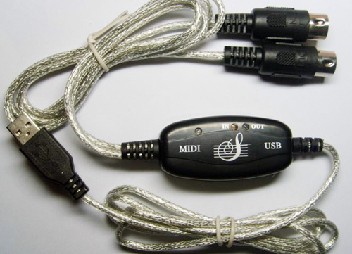
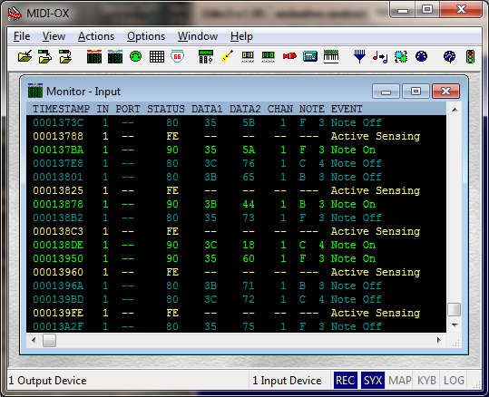
I had recently bought a Rock Band 3 Wii keyboard which has come down in price to around £10 with an intention to connect it to a cheap Chinese USB to MIDI interface cable for around £3 pictured above to do some MIDI experiments on my computer. Videos online demonstrated that connecting the IN connector to the keyboard and USB cable to the PC was all that was needed to use it, but I just couldn’t get it working. The Rock Band keyboard detected a MIDI cable and switched to MIDI mode, PC properly detected USB MIDI device, but there were no messages in the MIDI-OX application. That’s when I decided to open up the plastic casing to find a few surprises…
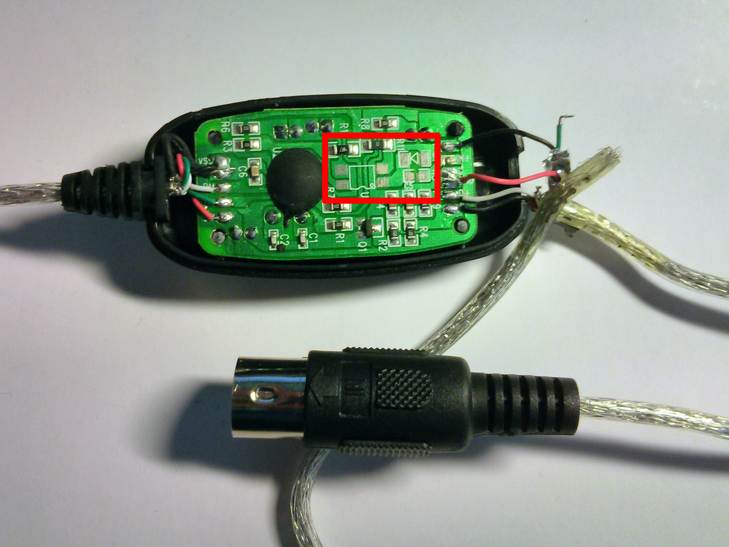
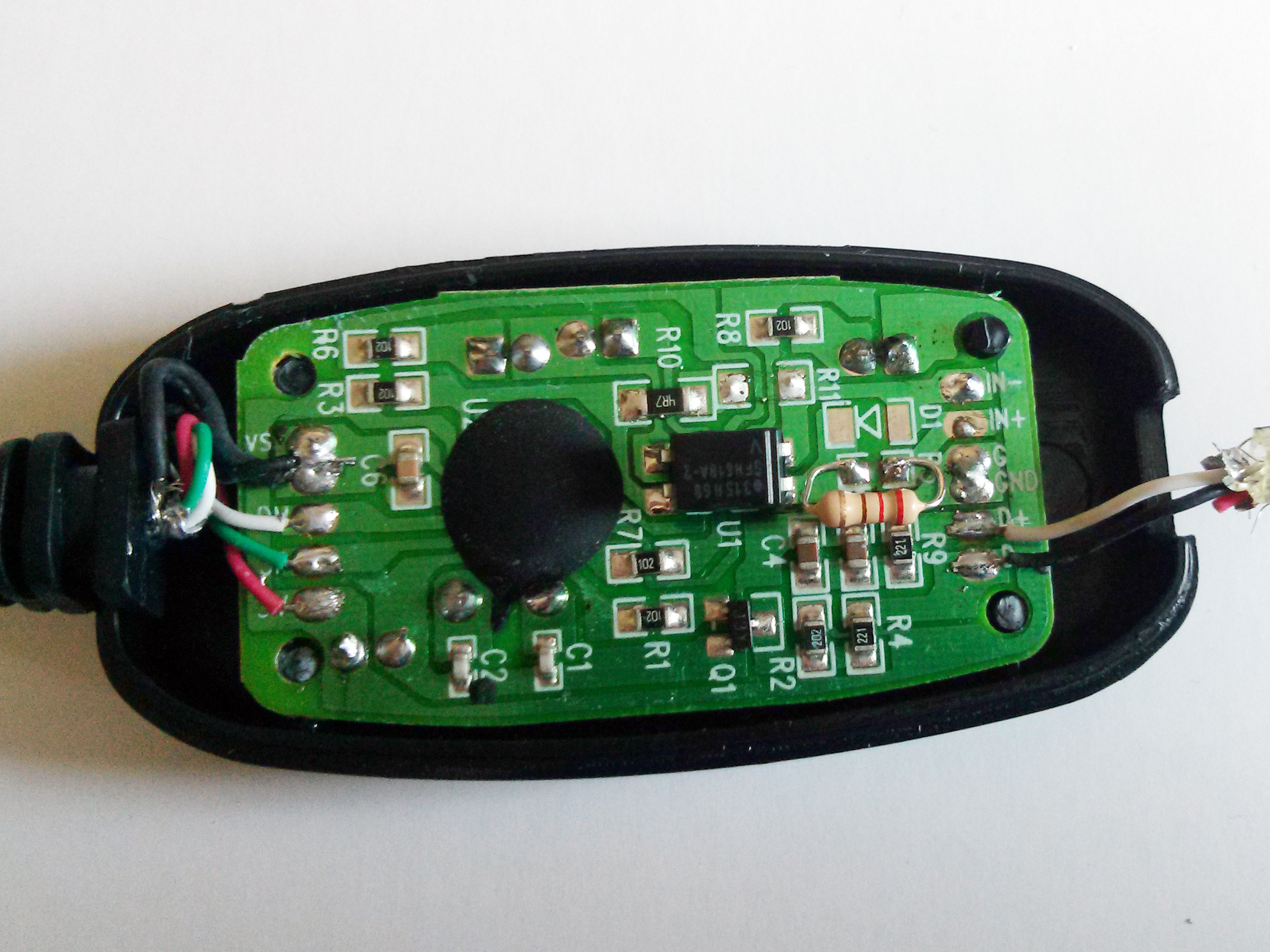
First thing I noticed, were the missing components on the board pictured in the red square. After further investigations, it turned out that the wiring was done completely different to the MIDI specifications. Here is a very rough schematic of how it’s done and how it should have been done:
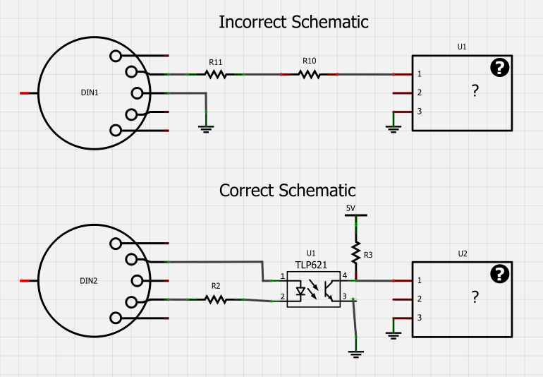
The MIDI specification requires an opto-isolator to completely isolate MIDI connected circuits. The USB cable did not have these parts populated and used a common ground for signal transfers. Rock Band keyboard probably was not expecting this. No wonder it did not work!
So, I went to Maplin and purchased a low-current opto-coupler SFH618-2 for £1.39. A quick assembly on the breadboard and a bit of soldering for ground, 5V and data lines to get to this:
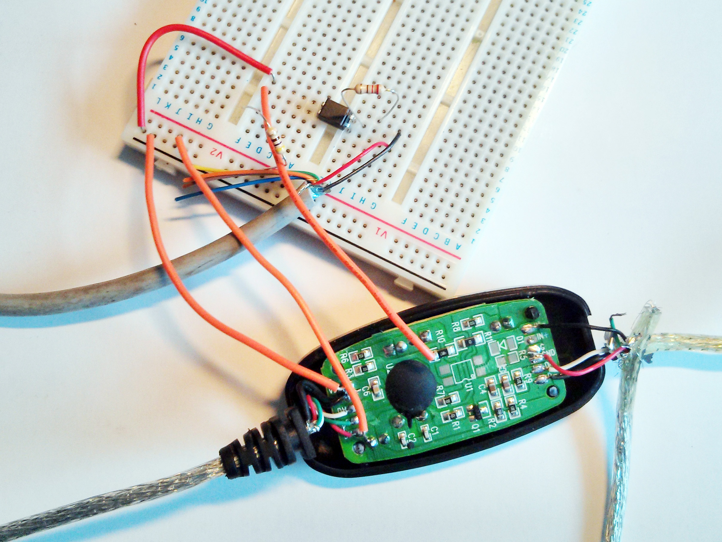
And it worked! It was finally time to populate the missing components:
- Got rid of the R11
- Soldered opto-coupler in U1 and it was a perfect fit for the pinout. I only had to shorten the pins to mount it as close to the board as possible.
- Soldered a 220 Ohm resistor in R5
- Removed the red DIN connector wire completely from GND connection and trimmed it
- Soldered the black DIN connector wire to IN- pad
- Soldered the green DIN connector wire to IN+ pad
The case fit back perfectly, though required some glue to hold in place and MIDI-OX finally came to life!
This USB MIDI cable might be a cheap and quick way to add USB enabled MIDI for Arduino, but I’m really wondering if it would have worked with any MIDI device at all due to incorrect wiring. You get what you pay for: some self assembly may be required.
Faced to the same problem with rockband keyboard and the same MIDI adapter, I only soldered a 330 Ohm resistor between IN- and IN+ , and it did the work.
Your solution is more complete and safe, as I understand.
Hmm.. that’s interesting. IN+ is not connected to anything at all when components are missing. Did you solder the green wire to the IN+ too?
No, I noticed that connecting a resistor only on the corresponding pins on the rockband keyboard made it switch to midi mode, so I tried adding the resistor to the adapter, and it worked.
I’ve posted photos of my modified adapter :
https://www.icloud.com/photostream/#A1G4TcsmGStdp5
Is the 330 Ohm Resistor the minimum or maximum resistance allowed? What other resistances are available for this fix?
I have the same adapter with the same components missing, but my PC would not recognize it. I have XP on computer. Any suggestions???
I also had a brief encounter with these things. It worked with my hardware but would freeze any midi communication while playing a midifile (I think it was saturating midi bandwidth when it happened)
Does the last image include all your fix done? or maybe did you forget another picture with the green and black soldered. thank you, i want to fix my midi cable because it doesnt work with the rockband keytar.
Yes, the last image does not show the wires soldered, just follow the instructions and you should be good to go:
Nice work!
I have a similar USB Midi adapter which also doesn’t seem to work. I opened it up hoping it would be the same as yours but it’s different.
Some pics:
https://dl.dropboxusercontent.com/u/1430251/13072013569-25.jpg
https://dl.dropboxusercontent.com/u/1430251/13072013571-25.jpg
https://dl.dropboxusercontent.com/u/1430251/13072013572-25.jpg
Any thoughts?
Yours looks like fun :) I think the best option for you is to take the Didier Arenzana advice in the first comment on this blog post. It’s difficult to tell which wires go where without rough schematic.
Don’t wish to be a pain, but could you give me a quick run-down on which lead came from where and where it ended up – I have exactly the same piece of kit as yours, but the green lead is not used in mine, so I suspect an ad-hoc scheme.
Thanks
The second pic from the top shows you how it was connected initially and then just follow the steps I wrote in the section starting with ” It was finally time to populate the missing components:”
So your green was not connected to anything? Mine is cut flush. That’s why I’m querying things, don’t want to make assumptions that might come back to bite me.
i can’t get it to work with an arduino,i think that the RX is the problem, because the communication led doesn’t light up and my computer can’t regconizing it, do you have any thoughts about it??
i mean TX sorry
Awesome! I bought four of these and was so disappointed.. Searched for a schematic to make my own but I’m so glad I can get all of these to work!
I have one of these interfaces that I have been trying to get working with a Behringer Ultradyne DSP9024 without much success, Will have a go at populating the missing components. Thing I’ve noticed is that when the ‘IN’ Din plug is in the ‘OUT’ socket of the DSP9024 then the power led on the midi usb cable is illuminated even when it’s not plugged into a usb port,
Nice work! Did you try to see wether you have better results regarding SYSEX?
On further investigation with mine I have found that in the DIN Connector only 2 wires are terminated and one of them is on terminal 2. At the pcb end of the cable the spare wire has already been trimmed back to the sheath. I’ve got the opto coupler and will also have to fit a new DIN plug on at least the ‘in’ cable. Most likely will also fit a new DIN plug onto the out cable as well just to make it look symetrical. Shouldn’t really have to do this, but stimulates learning about the MIDI interface. Maplin also sells the MIDI/ USB cable for about 20 quid— and you never know that one may still be lacking the opto coupler on the in cable.
ok the modification now completed and the interface reassembled. So first thing now the power led doesn’t come on when the ‘in’ plug is connected to the behringer DSP 9024. and the ‘input’ data led comes on when I do a memory dump which I can also read on the midi-ox in screen as sys data… now making some progress. The Behringer DSP 9024 windows editor still can’t see the midi ports. Next train of investigation was to load the windows editor onto a pc running windows XP and fitted with an audio card that has a midi interface- still the windows editor can’t set up the midi port so stumped for the moment and will give it some thought. The instructions for the Behriger Ultradyne are not too good and there aren’t any for the windows editor. Will update if I make any progress- one thing though is that for £3.00 and a few components this compares very favourably with other midi- usb interfaces.
hello. I’ve been buying these cheap usb devices and hacking them since they first hit e-bay back in the 1990’s. I’ve done a number of things with them, my favourite being an ultra cheap midi foot pedal using a cheap three button mouse (seven possible switch combinations). These midi usb devices used to have the optoisolater but for some reason (probably cost) they started leaving it off. The reason they can do that is simple. Almost all midi keyboards take the precautionary measure of including an opto-isolater in their design. It’s very rare that any midi device on the market would ship without one because not only is it part of the official midi spec, but it’s intended to prevent ground loops in complicated setups. If you can imagine a band doing an arena concert only to delay the performance because all the midi gear from different manufacturers is humming insanely due to ground loops. So almost never need the opto in the usb device.
Grant, ever come across one with the same design as mine?
Any idea where to add the opto-isolater to this?
Links the images again:
https://dl.dropboxusercontent.com/u/1430251/13072013569-25.jpg
https://dl.dropboxusercontent.com/u/1430251/13072013571-25.jpg
https://dl.dropboxusercontent.com/u/1430251/13072013572-25.jpg
Cheers
Thanks for the instructions. My lead looks the same as yours, so I followed your instructions, but nothing worked. Then I started experimenting and got it working with the Black & White leads on the IN+ & IN-.
The keyboard used is a 49 key Commodore MK10 with battery power. Playing into an iPad 2.
Hello, Thank you for the info.
I design midi controllers and I always go out of the MIDI standards. One of those standards is that there is always an opto coupler at the input of a midi device.
This Chinese crap does not follow these standards. Yet these MIDI USB cable work with eg Yamaha equipment, but apparently not with MIDI outs buffered with a 74HCT04.
Or are the midi standards changed now?
Regards Nico
hey guys.. i bought two of these thinking the 1st was duff.. 2nd was exactly the same.
works with :
yamaha psr 330
doesnt work:
yamaha sy85
yamaha pss-580
roland pc-200 mk II
grant – i would of thought something like the sy85 would have the optoisolater you talk about.. this is a strange one..
il try and have a go at fixing but go knows what im doing hah.. i do abit of soldering on laptops etc but i cant get my head round this for some reason. im sure its pretty straight forward eh?!
cheers
You can try this modification yourself but it does require a little nerve (and a good eye) as you have to trim and solder the optisolator into place and also getting the resistor pins bent just right and making sure the leads don’t touch any other components. then you have to cut the wires that go into the midi usb device and then using a pair of pliers you need to draw the whole cable through about 3/4 of an inch because you need to get the hidden green wire thats been trimmed at the factory. It needs to be long enough to reach the circuit board. You need the green and black wire and then trim the red down the way the green one was trimmed down. All in all, it’s an annoying fix as the wires are all over the place and it’s hard to get the circuit board positioned and god help you if you drag it out for ages and you strain the wires that come from the USB side and they break off. it can make you mad and frustrated if you’re not an electrical engineer (they’ve allready gone mad years ago so it’s easy for them). Also an old soldering iron with a blunt worn round tip will make it a pain if not impossible. Use good solder with rosin core (ideally very thin .6mm). But if you’re up for the challenge and if you have a maplin nearby ask them for optocoupler CY94. Clean the solder pads before you solder! Get them nice and bright. Solder the isolator the right way round! Don’t kill it with a lot of heat. Just a tiny bit of solder will do. Look at the pictures he provided to see which way it goes on the board because if you solder it backwards, getting it off the circuit board is harder than putting it on plus you’re likely to peel off the traces. And sadly even when done correctly it doesn’t always work properly. I’ve had it work “somewhat” at times. Midi notes go through the isolator but what comes out are the wrong notes with arbitrary midi channels (always something like, midi channel 1 “note on” and midi chanel 8 “note off”). Thats one for the bin. I salvage the midi and usb cables though. The midi standard was created to leave an aweful lot of options open and even if you do get it working properly it still might not work with all your keyboards. These things obviously skirt around the midi standard something terrible (to save money obviously) plus I don’t think the engineers who made it really knew what they were doing. And last but not least, if it doesn’t work out and you wreck it, don’t beat yourself up too badly It happens. At least you gave it a go. I think musicians in general follow the philosophy of, “it’s better to have loved and lost than to have never loved at all.” Good luck!
yes that is my way of thinking aswell :)
i do have a maplin close by.. i will go in and ask..
im not opposed to fiddly things.. and i do like messing around with stuff.. i just keep thinking im going to hook something up the wrong way (ground prob) and then electrocute myself haha
il give it a go anyways and if it doest work il just invest in a slightly higher price one for now.. thanks mate :)
I got the arbitrary note on/note off thing exactly as you described. Bridging r11 on the board cured it.
also doesn’t work with
novation remote 25 sl compact
Has anyone got this thing working with a Roland ED PC180a or a similar Roland controller of the era? No midi being received by the interface part of the cable, but Reaper and Kontakt are picking up the generic cable name.
Please help!
John
I bought one off amazon… £3.00.
So far it works note on off with iPad Air & apple CCK with old Radium 49 keyboard ( Maudio) & Axiom 49 2nd gen… Ok pitch bend works with some apps…and the controller seems to only send change messages from the middle position, but for the money…can’t complain, although I might have a go at the opto coupler addition..see if it smooth it out any.
Thanks a lot for sharing this valuable information. I made the recommended modification using a 4N35 optocoupler (I had a spare one in my drawer, but it has 6 pins so it is a little more difficult to solder on the board) and now my MIDI keyboard works fine.
WORK
SDT400
can this midi cable work for my Yamaha psr195 too?
I have one of these rotten devices too. It doesn’t work with my keyboard but the computer sees the USB interface.
I would make the modification but I am concerned about dangerous voltages in the adapter. There is a capacitor in the circuit and I know that capacitors store a charge for a long time. I am worried that I will get an electrical shock from accidentally brushing against the capacitor.
Hello Gavin.. there are no dangerous voltages to be concerned about. However, considering your skill level, I would suggest against tampering with the device and attempting to solder in an opto-isolator (i.e, optocoupler). You will most likely wreck the whole thing for good. it’s a difficult soldering job as you’re working with small SMD (surface mount devices). You need to do these little pinpoint perfect soldering spots to weld each of the four pins in place. you cant over heat the device either or it will wreck it. and if memory is correct (it’s been a while now) but I believe you also need to solder in a lead from one spot to the next. My first attempt totally failed and I’ve been into electronics for 20+ years. Shit happens. Good luck.
Hmmph well I have one that looks like the one “stuckinstandby” pictured.
I didn’t open it but it works fine
I’ve been trying to hack up a midi pedalboard with a picaxe and this midi-usb adapter for ages. I was getting very confused with ground problems that just didn’t make any sense. I even bought another adapter because obviously the first one was dodgy. Then I found this article and had an Ah-ha! moment and after only an hour on the bench everything was working fine after so much wasted time. It just explained everything that had been going on.
I’ve now got some dodgy pedals working fine with One Man Band. Thanks Arvydas !
Hi Lonnie,
Happy to hear it works and thanks for taking your time to write this nice comment :-)
Arvy
Hi guys, i’m from Colombia, excuse me about my english, is poor, but i hope that i make understand my problem, i bought this interface for work with a zoom g9.2tt guitar multiefect, surprise, that cable don’t work, i try to make the modifications but my cable shows an additional issue, when i plug in the usb port the green led turn on (in led), i look this wrong, must be the red led right (power led)?? when i touch the XTAL with my finger turns on the blue led (out led), like if be a electric short, obviusly don’t work, and for me that is a sad situation, i hope that you can help me, i will be very grateful with you.
I’m guessing that there is either a tiny little short in the soldering that you did, and you can’t see it with the naked eye. Or else, you purcahsed an opto-isolator (i.e., opto-coupler) that isn’t an exact match for the one that is required. it may appear to be pin compatible, but in fact, just won’t work. There is also, as I discovered an issue of overheating the solder joints and damaging the opto-isolator IC. Unlike a lot of other solid state devices, these are fairly suseptible to being destroyed by leaving the soldering iron on too long. Overall, they are very annoying and difficult to work with properly.
Thanks for answer, but, before the modifications that i make, the cable turns on only the green light, only the first time that i connect the cable on mi laptop turn on the red light, that’s drive me crazy… somehow, i will buy other opto. Thanks a lot
Hi, I had the same trouble, when i connect the usb, the green light turns on, and if i connect the midi on my keyboad the red light turns on too. So I try the midi os and noticed that all the time crazy signal are sending to in midi port…
Hello there. I’ve just got my MIDI to USB cable this morning. I’ve connected it to my PC and to Alesis D4 drum module. It does turn on a red LED light and the WIN7 recognized it as a USB A device in my DAW and has set the drivers. But it does not receive any MIDI note from Alesis, nor any other LED turns on when I hit the pad. Here are the pics:
https://plus.google.com/photos/102904355084234605437/albums/6103789622409581777
Can you give me a detailed, step-by-step advice what should I do? I can do a soldering etc. Just need to know exactly what I need and what to do.
Big thanks
Dragan it appears we have the same device. Same results with mine also. Have you succeeded in getting it modified to work?
Hi again
Pulling apart, inside is the same circuit and a very similar PCB to the original post (only the status LEDs are relocated slightly). The exact same components are missing, and the exact same mis-wiring has been done so I’ll get an opto isolator and make this thing good.
Trust yours was same, cheers! Geoff
Thank you very much, I used the 330 Ohm Resistence like Didier Arenzana said and my RB3 keyboard is running!
In my case, all wires al correctly solded, no opto- in the board, put the resistance in “+in” and “-in” and works like a charm!
Thaaaaaaaaaaaaaaaaaaaaaaaaaaaaaaaaaaaaaaaaaaaaaaaaaaaaaaaanks!
Just wanted to chime in that I used the resistor method with 220 Ohms successfully. The untouched wiring and PCB looked exactly like the unmodified unit of the original post, but unfortunately for me, the MIDI-IN cable had no green wire at all. I had to extract the DIN connector and pins so that I could solder my own wires to it. Modified, I had the black wire to IN -, red wire to GND, and my new green wire to IN + with a 220 Ohm resistor between IN – and IN +. In other words, DIN 5 to IN -, DIN 4 to IN +, DIN 2 to GND.
I just found myself in the same situation with a very similar Chinese made midi interface cable. In my case the Midi in port did not respond. I popped the case open only to find the black wire from the midi in din plug had broken off one of the ground pads. I soldered it back and the interface now works with my Korg C800 piano. I did not the same as you did about missing components including the all important opto isolator (labeled U1) and the protector diode and the two resistors (collector pullup and the series 220 ohm resistor feeding the opto diode. Just to save maybe 20 cents they ruined what might have been a decent mid interface at a very attractive price. Who can figure the inscrutable mind of the Chinese. Well they did manage to make it work on some midi device but as we have learned not all will accept this improper, non spec midi input. I have already ordered my parts from China via ebay to make my adapter the way it should have been. Opto isolators are about 30 cents each on the old ebone. China Post/ebay promoted deal with the US Postal Service/small packet service is incredible at sending a small package from China that I could not send across the street for that low a shipping charge. American businesses harmed again this time thanks to ebay.
Nice work!
Ich have exactly the same USB MIDI cable. When I connect my Roland Juno D to garageband (and swap IN to OUT and OUT to IN) garageband plays the keys of my keyboard. But when I hit several keys at the same time it gets strange (f. e. garageband plays sounds when I go off the key).
Can this have something to do with the missing parts in the cable?
Where can I buy a cable that is properly equipped?
Regards,
Gregor
Sometimes I have noted after buying a dozen of these cheap Midi adapters that the in and out cables have been reversed as labeled. The second big issue is the incorrect Midi In port which does not have the proper opto isolator and causes two problems. 1 is the load is not correct and 2. the signal from the midi out device is unbalanced which causes noise and crud to enter the midi adapter which means with some keyboards they will not work at all or maybe only intermittent notes may bet through. Some keyboards actually will work under this poor input arrangement but it is certainly not guaranteed. The midi adapter board has component locations for the missing opto isolator and resistors so to make it cheaper they left out these critical components. Buy a more expensive midi adapter or fix this one as I did buying my components directly from China off eBay.
Thank you Ken,
do you have a recommendation for a decent midi adapter?
I would try a Roland UM-ONE a their products always are properly engineered to match the midi standard. This costs about $40.
This article was posted out about a month after I abandoned fiddling with mine (similar but equally spaced lights), nearly two years ago! It kinda worked with my MK-149 keyboard with some data getting through but a lot of spurious messages being “received” and I rather assumed it was a Microsoft not being bothered to support MIDI properly.
Even more foolishly I didn’t even bother opening the case (thought it would be sealed and need beating open) or I might have worked it out for myself!
On the upside, I actually had an opto-isolator sitting on the desk that I’d rescued from something on the off chance it might come in handy :-)
Handy tip: Drilling through the pads with a 0.8mm bit makes soldering the opto easier. It also means the resistor can sit on the plain side of the PCB.
confirmed working with 220 ohm and opto 4n35! Unfortunately, the included MIDI cable only had 2 wires, so I had to replace the MIDI IN cable…
All I had to do was to unplug this midi cable from the USB and the my piano (which I am using a Yamaha W5 Version 2 Synthesizer) and reconnected the midi cable back into the piano you know put the in cable in the out input and the out cable in the in input and then I put the USB in and it recognized my piano again and I got it to work through Fl Studio 11 by enabling the midi device in the midi settings by changing the “port” to 1.
What kind of opto-coupler i can use ? I can’t find any of this :(
I have a dim-4 thing with b1038 817c code on it , what is it ? :D
i bought usb midi cable today. this is the cable.
http://i58.tinypic.com/ng2ihe.jpg
and i try to send syx file to my roland xp 80 using SendSX software. it shows data is sending. but data is not receive to keyboard. i only want to use this cable for send my syx file to keyboard and get keyboard data to pc. can i fix this cable? please help… thanks.
http://i61.tinypic.com/vgmopg.jpg
http://i60.tinypic.com/10zwob4.jpg
can i use this opto coupler??
http://i59.tinypic.com/5u0dwy.jpg
hi guys
i have midi cable//china made
i bought it to use it for midi data transfer to restor the sound in my korg x3..and using midiox also
but i have a problem
if i using the keys as controller it work fine and if i use it also to save sound from my keys to my pc it work also
but when i using it to load from my pc to my korg its not work
are you think thats from the same problem from the cable or its not same?
Can you share any tricks on how to open the case?
There’s also a diode 1N914 between the IN+ and IN- on midi.org schematics. Why did you leave it out? Would it help anything?
Thanks for taking the time to post this. It’s exactly what I need :)
Hi guys, I have a question bout optocoupler, whether it has to be SFH6106-2T or can it be anything else: for instance LTV817S or something similar.
I haven’t checked the specs for that one, but I did check the specs of the PC817. I’m supposing, though, they are the same and will work.
I`ve bought SFH6186-3T. Everything is ok.
In case of problems when using slower optocoupler (optocoupler PC817, 18uS switch time, 80kHz cutoff) adjust value of R3 (in my case around 220 Ohm only). The best way is to use oscilloscope or at least to observe the LED diode on IN).
I used SFH6186-3, 220 ohm, and 1n4148 diode. Result is almost as poor as before. Single key stroke gets through, but multiple simultaneous do not. Bugger…
The DIN plugs are also complete c… in this thing. The shield rings are just pressed to the plug, and get off with a bit of pulling. Maybe the diode was too much, maybe I should fix the groundings too.
BTW, do please notice that MIDI 1.0 specs says that MIDI IN plug pin 2 should not be connected, unless it’s done via 0.1µF capacitor. (https://www.midi.org/images/downloads/ca33.pdf)
Still, it was fun to try to fix this adapter! Thanks for this article, Arvydas!
Hi,
I’ve that cheap USB MIDI cable and I’ve noticed that sometimes some notes are lost.
I’ve added optocoupler and other stuff but things do not change!
I’ve to change optocoupler or this problem will be persistent ever ?
Thank you,
Lude
Yes, it will persist forever. If you need more than one note, these dirt cheap controllers are XXXXX. Save money, time and nerves, and buy a decent controller, or make one yourself. Take an Arduino with USB-HID support (no, not those dirt cheap copies), or a Teensy, connecting it to MIDI with those optocouplers, diodes and resistors, is a way better option. But it needs more than some self assembly.
Recently I built it. Many experiments and more problemos. You forget throw the optocoupler 6N35 and 4N25, or xNxx…. are all wrong shit! All of these appeared to be unreliable transfer and imperfect.. To needed use high-speed optocoupler with digital output , type PC900 or H11L1 ! Very very good succed is H11L1.
hi,
here is the data sheet for the USB to MIDI CH345 with schematics for different options:
http://www.gwerder-elektronik.ch/files/CH345DS1.pdf
i got two of these shite thingis. now i’m clueless how to solder a pc900 optocoupler on the pcb, because it just have 4 patches and the pc900 6. i’m also not sure if my problem can get solved. i just get random midi events when i connect the midi-in cable to my master keyboard.
so, mirex, please send some images, please.
thanx,
tx